3 Easy Steps to (almost) Curing Type 2 Diabetes

Original paper: Synthetic beta cells for fusion-mediated dynamic insulin secretion


Type 2 diabetes currently affects ~ 410 million people worldwide. It is a chronic condition caused by dysfunctioning beta cells in the pancreas. Beta cells normally secrete insulin in the pancreas to regulate blood glucose levels, and the loss of beta cell function can lead to hyperglycemia (i.e. high blood sugar), a condition with complications such as blindness and heart disease. The traditional invasive treatment involving direct insulin injection is a painstaking, never-ending process as it doesn’t properly regulate the dynamics of beta cells, just treats the symptoms. Modern treatments involve cell therapy in which functioning beta cells are transplanted from a healthy person, but this therapy faces serious challenges such as finding the right donor and suppressing the immune system after the transplantation. In this post, you will read how Chen and co-workers design an artificial version of beta cells that bypass the shortcomings of conventional cell therapy.

In our body, beta cells in the pancreas are responsible for monitoring and balancing our blood sugar level. When glucose levels are low (hypoglycemia, low sugar levels), these cells rapidly secret a polymeric (see note [1]) form of glucose. With high glucose levels (hyperglycemia) a hormone called insulin is secreted to bring down the concentration of sugar in the blood. Any disturbance to these cells, either through the body attacking itself (Type I diabetes, see note [2]) or genetic risk factors, can compromise the function of the beta cells, resulting in hypo- or hyperglycemia.

A4-fig1
Figure 1. The schematic of the vesicle-in-vesicle system. The giant micron-sized lipid vesicle (the OLV) encapsulates the machinery components for the insulin release, including the smaller vesicles that carry the insulin (ISVs). The image is taken from Chen and colleagues.

In this study, the researchers mimic the cell’s machinery in beta cells that sense sugar and signal a response inside the cell. This artificial system features two differently sized lipid vesicles (see Figure 1). The larger vesicle is about a micron in size (millionths of a meter) and is called the outer layer vesicles (or OLVs). It acts as the body of the artificial beta cell, encompassing the necessary machinery to regulate the insulin release. The second, smaller lipid vesicles, a thousand times smaller than the OLVs, are held inside the OLVs and are thus called inner layer small vesicles, or ISVs. These ISVs encapsulate the insulin hormone inside.

The system acts like a computer code with a conditional “IF” command to decide whether it needs to respond or stay inactive. IF the glucose levels outside of the OLVs are normal or below normal, no signal is induced. However, IF the glucose level increases beyond the signal-inducing concentration (which can be easily tuned by chemical modification, see below) then the signal is triggered, resulting in insulin release. The entire system consists of machinery to perform three distinct steps.

The first step is the glucose sensing step. Using a glucose transporter membrane protein, the OLVs sense and absorb the glucose from their surroundings. Next, the uptaken glucose is converted into protons using two enzymes that are inside OLVs (see note [3]). Changing the concentration of protons in a liquid alters its pH. This variation in the pH of the microenvironment inside the OLVs initiates the second process.

The second step is the response. For this step to proceed, the ISVs need to get close to the inner wall of the OLVs. The surface of the ISVs, however, is decorated with giant linear molecules that prevent the ISVs from getting close to the OLVs’ inner wall. But, with a high glucose concentration, the environment inside the OLVs becomes acidic, as described above. Under acidic conditions, the ISVs’ protective coating is engineered to leave the surface of ISVs, and this step is called the de-shielding step. Now ISVs close to the inner wall of the OLVs can merge or “fuse” with the OLVs. However, the two vesicles will still not reliably fuse together, so the researchers implement an active fusion mechanism (see below).

The third step is the release of the insulin. Remember that the nanosized vesicles are already loaded with insulin. The authors use two complementary DNA strands: one on the surface of ISVs (pink strands in Figure 1) and the other one on the inner wall of the OLVs (red strands in Figure 1). These complementary strands are like a key and lock that only open when the right key is inserted in the right lock. When the environment is acidic, the ISVs are free (de-shielded happens) to reach to the inner wall of the OLVs and through the DNA strands, ISVs bind to the wall. When this binding happens, the fusing event follows. Upon the fusion of ISVs to OLVs, the insulin is released.

When the surrounding glucose levels decrease, fewer protons are created inside the OLVs, and a second membrane protein called Gramicidin A, which is constantly working to expel protons from the OLVs, can balance the pH inside the OLVs. When the pH becomes neutral, the giant linear protective molecules that were floating around when media was acidic find the ISVs and re-stick to them. Thus the cascade of events of glucose sensing, deshielding, and insulin release then ceases once the pH returns to the point that the deshielding doesn’t happen.

fig2
Figure 2. The insulin release as a function of time in diabetic mice treated with artificial beta cells and the control groups. The figure is adapted from Chen and colleagues.

To test how their system actually responds in a biological medium, the authors apply a gel under the skin of mice that contains the OLVs. For a group of diabetic mice, this artificial beta cell system showed a significant effect on the measured insulin levels in the mice blood. For control groups; (i) with no insulin ($latex A \beta C_{no insulin}$), (ii) with no lipid fusion system $latex A \beta C_{PK/PE}$ (PK and PE are DNA molecules that mediate the fusion process), and (iii) with no glucose sensing machinery $latex A \beta C_{no GSM}$, the insulin release was minor over the course of 10 days (see Figure 2). But when the insulin-loaded artificial cells were administered, the mice’s insulin levels increased remarkably over the control cases.

All in all, Chen and colleagues manage to release insulin in a controlled manner. There’s no need to evade an organism’s immune system–the OLVs don’t provoke an immune response. There’s also no need to inject insulin–it’s released automatically when needed. This work gives hope of drastically improving the lives of the nearly half a billion people worldwide suffering from diabetes.


[1] You might be asking: why do pancreatic cells secrete a polymeric form of sugar in response to low blood sugar level?! Well, which one is faster and more effective to you? Releasing one-by-one a single sugar, or releasing one-by-one a bag full of sugar molecules (the polymeric form). When this polymer leaves the cell quickly, it bursts (dissociates) into single sugar molecules, later to be absorbed by relevant cells.

[2] Under some circumstances that might be due to genetics, the body’s immune system attacks the beta cells and destroys them. These are called autoimmune disorders.

[3] Glucose oxidase (GOx) and catalase (CAT) are working in parallel to transform the glucose signal into protons. GOx, with the help of an oxygen molecule, converts the glucose to gluconic acid releasing a proton. But there is a by-product of this reaction which is not favored. The hydrogen peroxide ($latex H_{2}O_{2}$) produced is very active that can mess up all the molecules inside the giant vesicles. With a nice trick, the researchers simultaneously convert the hydrogen peroxide to oxygen by adding CAT enzyme. Now, this is feeding two birds with one seed. Getting rid of ($latex H_{2}O_{2}$) while providing the oxygen for the GOx to do its job.


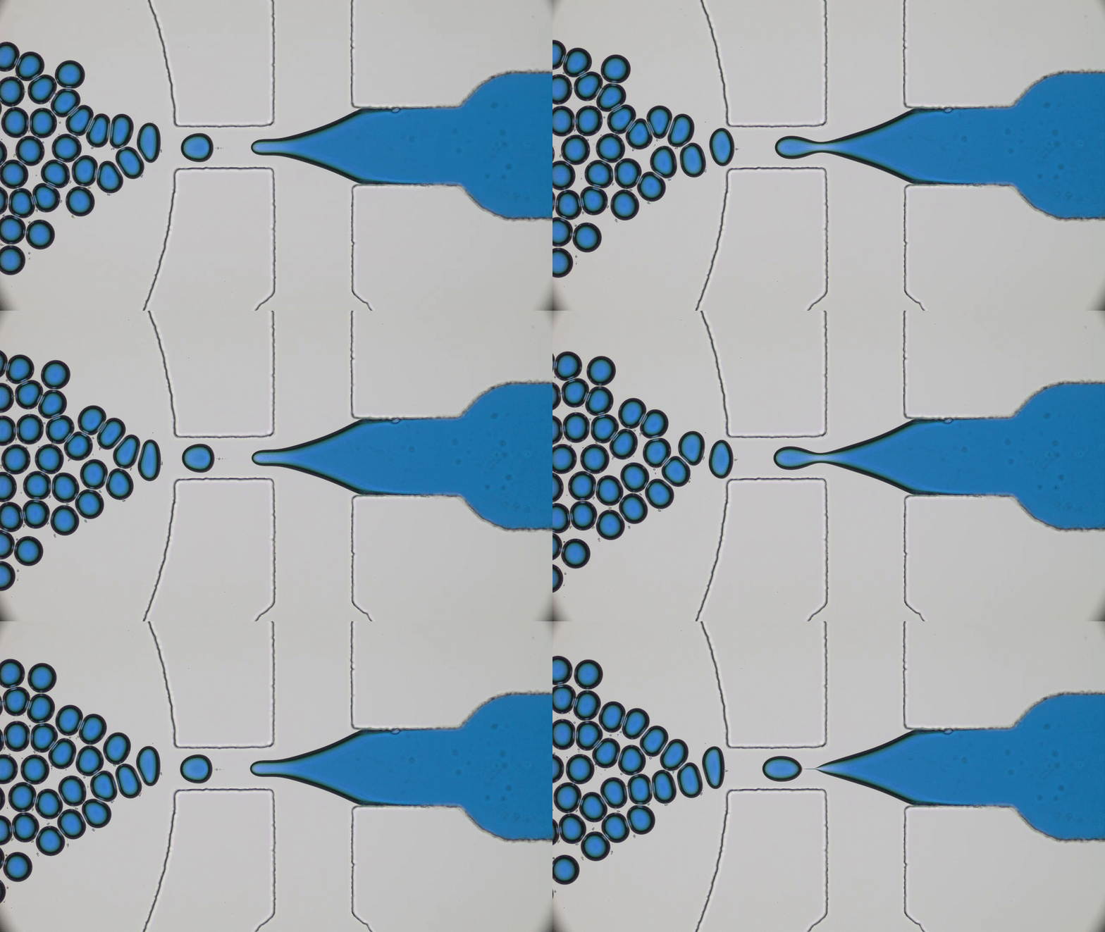
Dripping, Buckling and Collapsing of a Droplet

The scale bar is 20 micron.

Original paper: Mechanical stability of particle-stabilized droplets under micropipette aspiration


Most of us have had the childhood experience of blowing bubbles. But have you ever wondered how bubbles form and what keeps them stable? The key to making bubbles is surface tension, the tension on the surface of a liquid that comes from the attractive forces between the liquid molecules.  Water has a very high surface tension (that’s why bugs can walk on water) making it difficult to stretch to form a thin water layer that we see when bubbles form. By adding soap to water, we can lower the surface tension of the water, allowing us to stretch this water-air interface to form a thin water sheet. As you blow more and more air into a bubble, the bubble will grow larger and larger as the thin layer stretches. Eventually, you’ll reach the limit of the added stretchiness, and the bubble will burst, engraving in your memory its fragile nature.


Fig1-1
A typical air bubble made out of a water-soap mixture (Figure courtesy of Gilad).


In soft matter, sometimes scientists utilize materials such as solid macroscopic particles instead of soap molecules to reduce the surface tension of an interface. Using particles to stabilize an interface allows them to tailor the mechanical and chemical properties of the interfaces to fabricate capsulesFor instance, if a capsule needs to travel in blood-stream for therapeutic purposes, it must be tough enough to withstand blood pressure without rupturing. But if we make such a capsule how can we measure its mechanical response?

In this post, we’ll look into the work by Niveditha Samudrala and her colleagues on measuring the mechanical properties of a particle-stabilized interface. They utilize a direct approach of applying force on such a stabilized interface to study its mechanical response that has eluded earlier techniques. Knowing the stiffness of these particle-coated interfaces, say in the form of capsules, would enable us to use them for different controlled-release applications such as treating a narrowing artery [1] as well as tune them to have different flow properties. 

The authors use tiny (smaller than a micrometer!) dumbbell-shaped particles with different surface properties to stabilize an oil-in-water emulsion (see note [2]). Here instead of a thin layer of water sandwiched by the soap molecules, the water-oil interface has been stabilized with micron-sized particles. This stabilization technique will render higher mechanical properties to the interface. Droplets stabilized in this way, known as colloidosomes, have been shown to be capable of encapsulating a wide variety of molecules.

The researchers characterized the particle-stabilized droplets using the micropipette aspiration technique. To understand this technique, imagine picking an air bubble with a straw. What you need to do is to approach the air bubble and then apply a gentle suction (or aspiration) pressure. When the suction pressure becomes larger than the pressure outside of the droplet, then the droplet gets aspirated into the straw forming the aspiration tongue (Figure 1A). Similarly, in the micropipette aspiration technique, a glass pipette (the straw) with an inner diameter of $latex R_p$ is usually used to aspirate squishy stuff, such as cells, vesicles, and here droplets. 

To obtain the tension response, therefore the toughness of an aspirated interface, we need to consider the pressures applied to the interface. Let’s consider an aspirated droplet as shown in Fig 1A at mechanical equilibrium (which means the sum of all the forces is zero). We know that each interface has a surface tension acting on it (See Fig 2a). In our bubble example, I mentioned that the soap molecules tend to gather at such interface to decrease the tension (See Fig 2b). But when there are other forces acting on the interface in addition to the presence of the molecules, such as the suction pressure in our case, the tension of the interface now comes from both the surface tension and the suction force. We call this total force the interfacial tension (See Fig 2c). The Young-Laplace equation can be used to relate this interfacial tension to the pressure applied to the interface (Fig 1-B3). 

Fig1
Fig1. Schematic representation of the aspiration technique (A) and the Young-Laplace equations obtained at both interfaces of the outer edge of droplet and tongue inside the pipette (B). $latex P_{atm}$ is the atmospheric pressure set to zero, $latex P_{droplet}$ is the pressure inside the droplet. $latex P_{pip}$ is the suction pressure. $latex R_{v}$ is the radius of droplet outside the pipette and the $latex R_{p}$ is the pipette radius.

When the molecules, or particles in our case, are forced to pack tightly together they oppose the compression force. This opposition is felt at the interface by a pressure called surface pressure (see Fig 2c). Under the interface tension and the surface pressure, the new net interfacial tension is defined as:

$latex \tau=\gamma_{0} – \Pi$.

where $latex \Pi$ is the surface pressure, $latex \gamma_{0}$ is the interface tension which is constant for a given interface. 

In this study, Samudrala and her colleagues show that there are two critical pressures after which instabilities form at the interface resulting in droplet dripping into the pipette and buckling respectively (Fig 2d). They conclude that the dripping happens due to the transition of the interface from a particle-stabilized interface to a bare oil-water interface resulting in a sudden suction of tiny oil droplets (basically the droplet drips at this point, see Fig 3B, blue and 3C).

The second instability is the buckling which the researchers propose happens when $latex \tau$ tends to zero. Now let’s see how buckling happens.

interface
Fig 2. The schematic of a particle-stabilized water-oil interface under different load is shown. (a) shows the bare water-oil interface. This interface has a constant, material related surface tension, the $latex \gamma_{0}$. (b) depicts a particle-coated interface. The aggregation of the particles at the interface, decrease the interface tension to a new value of $latex \gamma$. (c) the particle-coated interface is compressed from both ends. This case happens in our case when the particle-coated droplet is stretched (see the text). (d) the compressed interface reaches a critical pressure upon which the net tension of the interface is zero and the buckling happens as the interface cannot no longer endure the imposed force.

The dripping at the first critical pressure decreases the volume of the particle-coated droplet, but note that the surface area is constant because neither particles leave the surface nor the free ones join the droplet (the latter argument is assumed). The continuation of the increase in suction pressure plus the volume lost in the dripping step results in the buckling of the interface (Fig 3b red and 3E, also see note [3]). When the authors aspirate the bare oil droplets as well as droplets stabilized by small molecules, they only see the sudden droplet disappearance with no shape abnormalities due to the fluid nature of the interface rather than solid-like nature for the particle-stabilized case. But why does the buckling happen? 


Screen Shot 2017-11-06 at 17.55.45
Fig 3. Evolution of instabilities of a particle-coated droplet under tension. (a) shows the schematics of the particle-coated droplet being aspirated. (b) Change in aspiration length as a function of suction pressure. Blue line remarks the capillary instabilities. Red line shows the elastic failure of buckling process. (c & d) are the images of capillary and buckling instabilities respectively. (e) shows the case when the suction pressure is above buckling pressure at which the particle coat fails (the figure is adapted with no further change from the original paper).

Recall how we defined the net interfacial tension above; $latex \tau=\gamma – \Pi$. The authors hypothesize that upon suction of a particle-stabilized droplet, particles jam at the interface of the droplet outside of the pipette, creating a high surface pressure. When this surface pressure approaches $latex \gamma$, the net tension becomes zero ($latex \tau=0$, see fig 2d and note how the interface tension is opposed by the surface pressure due to repulsion between particles). When an interface possesses no tension, it means that the interface can no longer bear any loads. Considering any sort of defects or irregularities due to nonuniform particle packing, for such interfaces deformations such as buckling will form. Now, let’s see how the authors test their hypothesis.

The authors observed that at the tip of the tongue, there is a very dilute packing of particles in such a way that the interface to a good approximation resembles the Fig 2a, a bare water-oil interface. With this observation, one can safely assume that the interfacial tension, the $latex \tau$ is equal to the oil/water interface tension, the $latex \gamma$ and write the Young-Laplace equation across the tip of the tongue (see Fig 1B-(1)): 

            $latex P_{droplet} – P_{pip} = \frac{2\gamma_{0}}{R_{p}}$

where $latex R_{p}$ is the radius of the pipette and is fixed. The authors experimentally show that for a range of droplet size ($latex 10\ \mu m < R_{droplet} < 100 \ \mu m$), the droplet pressure right before buckling varies very close to zero (in above equation all parameters are known except the $latex P_{droplet}$, which is calculated when we put $latex P_{pip} = P_{buckling}$). Therefore, considering the equation (2) in Fig 1B, the net tension would be zero (see note [3]) and with this, the authors correlate that the reason for the formation of buckling is the net-zero tension of the interface.

Taking it all together, we saw that for a droplet with solid-like thin shell, the mechanical response is completely different from the bare or the molecule-stabilized interface. A fairly rigid interface undergoes buckling due to its net tension tending to zero and knowing the threshold of buckling will enable us to tune the mechanical properties of such droplets for different applications from load-caused cargo release (see note [1]) or emulsions with varied flow properties. Imagine if we encapsulate a fragrance in our air bubble, which upon rupturing will release the scent. Now, wouldn’t it be nice if we could control the toughness of this bubble or similar architecture to rupture under a specific condition that we desire (see note [1])? 


[1] In a disease called atherosclerosis, the arteries narrow down due to plaque buildup. In this narrow region, the blood pressure is higher than the normal region of the artery. So one can use this pressure difference to crack release the relevant drug from the capsule only in the narrow regions of the artery to dissolve the plaques away. Neat!

[2] If we apply a shear force on a mixture of two or more immiscible liquids in the presence of a stabilizing agent, we produce an emulsion and the stabilizing agent is called an emulsifier. The particles show a significantly higher tendency to gather at an interface in comparison to amphiphilic molecules. Thus, particles are strong emulsifiers. If we mix lemon juice and oil, soon after stopping the mixing, the two solutions will separate. Now, if you add eggs, you stabilize this mixture (egg works as an emulsifier) and you get Mayonnaise!!

[3] The authors report that for particle-stabilized droplets they observed different deformation morphologies such as wrinkles, dimples, folds and in some case complete droplet failure. They attribute this diversity to the non-uniformity of particle packing at the interface. But what is interesting to me is when they decrease the suction pressure, the droplets go back to their original spherical shape and then upon the second aspiration, the deformations happen at the same exact location as were for the first aspiration. This means that during the suction, there is limited particle rearrangement (Watch here).

[4] We can easily set the atmosphere pressure to zero before aspirating the droplets, thus here the $latex P_{atm} = 0$.

Brick-by-brick to Build Tiny Capsules

Original paper: Colloidosomes: Selectively Permeable Capsules Composed of Colloidal Particles


Disclosure: The first author of the article discussed in this post, Anthony Dinsmore, is now my Ph.D. advisor. He did his postdoc at Harvard University a while ago, and consequently, I was never involved in this work.

In past two decades, several approaches have been developed and optimized to encapsulate a wide variety of materials, from food to cosmetics and the more demanding realm of therapeutic reagents. Inspired by biological cells, the first attempts were to use either natural or synthetic lipid molecules to form encapsulation vessels, the so-called liposomes. Then, with the increasing awareness of controlled release of cargo, especially for therapeutic purposes, advanced materials such as polymers were developed to form carrying vessels. There has been an enormous progress in encapsulation technologies, however, these methods can be limited in their applicability regarding encapsulation efficacy, permeability, mechanical strength, and for biological applications, compatibility. In this article, Anthony Dinsmore and his colleagues introduce a new platform and structure to encapsulate almost all types of materials with finely controlled and tuned properties.

Colloidosomes

An emulsion is produced typically by application of a shear force to a mixture of two or more immiscible liquids like the classical water-oil mixture. The resulting solution is a dispersion of droplets of one liquid in the other continuous liquid. In such case, an interface between the fluids exists that would impose an energy penalty on the system. Therefore, the system will always attempt to minimize it, in essence by reducing the area of the interface that is to merge the similar liquid droplets. Amphiphilic molecules are known to segregate in such interface to further reduce the energy and to inhibit the merging of droplets.  This segregation is not limited solely to molecules though. Solid particles tend to jam in the interface for the same reason to stabilize the emulsions. Inspired by the idea of particle-stabilized emulsions, which are known as Pickering emulsions, Dinsmore, and his colleagues have developed capsules made of solid particles. They adopt the name “Colloidosomes” by analogy to liposomes and demonstrate how the arrangement of these particles can be manipulated and controlled to achieve a versatile encapsulation platform.

Fabricating the Capsules

Colloidosomes are prepared first by making the emulsion in which the continuous phase contains the particles. For instance, in water-in-oil emulsions (“w/o”), water droplets become the core of the colloidosomes and particles are dispersed in the oil phase. Gentle agitation of such system results in particles being trapped in the water-oil interface (see Fig.1). The authors summarize the capsule formation in three main steps:


Screen Shot 2017-10-17 at 01.01.10
Fig 1. The colloidosome formation process is illustrated schematically in three steps. (A) a water/oil emulsion first is created through gentle agitation of the mixture for several seconds. (B) Particles are adsorbed to the w/o interface to minimize the total surface energy. Through sintering, van der Waals forces, and or addition of polycations ultimately the particles are locked in the interface. (C)In the end, the particle-stabilized droplet is transferred to water via centrifugation.

(a)  Trapping and stabilization. When the water-oil interface energy surpasses the difference between particle-oil and particle-water interface energy, particles are absorbed to the water-oil interface and become trapped due to the presence of a strong attractive well. This differs substantially from the case where particles were adsorbed to the interface via electrostatics, which requires the droplets to be oppositely charged to attract the particles. The packing of the particles at the interface is adjusted by controlling their interactions. Typically, the electrostatic interaction between particles, due to their surface chemistry, is utilized to stabilize the packing of the particle. For instance, in this study particles are coated with a stabilizing layer which in contact with water turns into a negatively charged layer.


(b)  Locking particles. To form an elastic and mechanically robust shell, the particles must be locked in the interface. This results in an intact capsule that can withstand mechanical forces. One way to obtain such elastic shell is to sinter the particles in place. Sintering is a thermally activated process in which the surface of particles melts and connects them to each other. Upon this local melting, the interstices among particles begin to shrink. With longer sintering times, it is possible to completely block the interstices, which results in very tough capsules with extremely high rupture points.  In this study, particles with 5 minutes of sintering yielded a 150 nm interstices size, and with 20 minutes, almost all the holes were blocked. By using particles with different melting temperatures, the sintering temperature can be adjusted over a wide range; this might be advantageous for encapsulants incompatible with elevated temperatures. Other ways of locking particles are electrostatic particle packing and packing via van der Waals forces. In the former case, for instance, a polyelectrolyte of opposite charge can be used to interact with several particles to lock them in place. In the latter case, for the van der Waals force to be effective, the steric repulsions and barrier must be destroyed so the surface molecules can get close enough for the London forces [1] to be strong.


After the Colloidosomes are formed, through gentle centrifuging, the fluid interface can be removed by exchanging the external fluid with one that is miscible with the liquid inside the colloidosome. In this step, having a robust shell to withstand shear forces crossing the water-oil interface is very important. This process ensures that the pores in the elastic shell control the permeability by allowing exchange by diffusion across the colloidosome shell. Now, with these steps and knowing parameters such as surface chemistry and locking condition, a promising system with characteristic permeability or cargo release strategies can be designed.


Tuning Capsule Properties; Permeation and Release

The most important feature of a colloidosome, as a promising encapsulant, is the versatility of permeation of the shell and or the release mechanisms. Sustained release can be obtained via passive diffusion of cargo via interstices that can be tuned via particle size and the locking procedure. With the mechanical properties of capsules optimized, shear forces can be used as an alternative release mechanism. For instance, minimally sintered polystyrene particles of 60 microns in diameter have shown to rupture in stresses that can be tuned by sintering time over a factor of 10. What makes the colloidosomes even more interesting is that one can choose different particles, with different chemistry, to have an auxiliary response, such as swelling, and dissolving of particular particles in response to the medium. It is also conceivable if one coats the colloidosome with the second layer of particles or polymers to improve or sophisticate the colloidosomes response. The latter can also mitigate the effects of any defect in the colloidosome lattice.

        With this unique platform, Dinsmore and colleagues stepped into the new realm of encapsulating materials of all kind. From therapeutic cargos to bioreactors, the chemical flexibility and even the ease of post-modification would expand the cargo type beyond molecules. For example, the authors show that living cells can be encapsulated in colloidosomes. Well, you may wonder, WHY? Imagine a protective shell around cells that keep them out of the reach of hostile microorganisms without compromising the cell’s vital activities such as nutrient trafficking and cell-to-cell crosstalk. 


[1]  London forces arise when the close proximity of two molecules polarizes both molecules. The resultant dipole work as a magnet to glue molecules together. Therefore, London forces are universal forces (and part of van der Waals forces), which takes effect when atoms or molecules are very close to each other.

When Bending Comes at A Cost: Vesicle Formation and Size Distribution

Original paper: Formation and size distribution of self-assembled vesicles


I’m going to start this post with an experiment. Find a piece of smooth and unwrinkled A4 or paper of a similar size, and hold it by gripping an edge between your thumb and forefinger. Due to the gravitational force, the paper is pulled down and is bent. Now crumple the same paper, then unfold and hold it by the edge again. What happened? The paper can now resist gravity! This wrinkling strategy is a simple trick to improve the mechanical response of a thin 2D sheet. Astonishingly in biology, by such simple ways, cells tune the mechanics of their thin membrane to form tiny capsules called vesicles in order to uptake nutrients, to dump waste, and to communicate. But how such a thin sheet can address all these needs? What are the mechanisms behind these tunings? Are there consequences other than mechanical improvements? In today’s paper, Changjin Huang and colleagues investigate the critical parameters governing the vesicle formation process (or vesiculation) and the size distribution of vesicles.

The Vesiculation Process

A class of molecules called amphiphiles contain two parts: a water-loving (hydrophilic) head and a water-fearing (hydrophobic) tail. When amphiphiles are dispersed in water, the hydrophobic tails are frustrated and get together (self-assemble) to stay away from water. Based on the geometry of these two parts, different structures emerge (see note [1]). One such structure is the bilayer structure (Fig. 1A).

Slide1
Fig. 1. A through D is the evolution of a vesicle, starting from a membrane patch (A) bending to (B) and closing at (C ) to form vesicles. The spontaneous decrease in systems’ energy by closing the patch is opposed by the energy required to bend the patch. The competition between these two energies is determined by factors such as patch size(l), membrane thickness (d), curvature (1/R), and bending stiffness ($latex k_b$). Combination of any of these factors can result in either or combination of above morphologies.

A bilayer structure composed of two layers of molecules with the hydrophobic tails turned inward (Fig 1A). This bilayer arrangement still is not the favored structure, since the water-fearing tails are exposed to water on the edges of the bilayer. An energy is imposed on the system by such exposure. This energy is called the interface energy and usually is shown by ?. This interfacial energy is the only driving force for the bilayer to bend in order to minimize the system’s energy. Thereby, the bilayer attempts to bend into spherical structures (Fig 1B & C).  But bending comes at a cost! The system needs to exert force to bend the bilayer. In other words, energy is required to curve the bilayer. In this work, Huang and colleagues model this process with an energy-minimization approach to realize the critical parameters that determine the fate of this competition.

Parameters Affecting the Vesiculation

The quick paper experiment highlighted the essential role of local curvature in sheet’s rigidity, but that’s not all. The authors of this study theoretically demonstrate that besides local curvature, membrane thickness, membrane bending resistance (bending stiffness) and the membrane patch size (size of the paper sheet) all play a crucial role in the vesiculation process. When the authors considered the role of membrane thickness, they could predict morphologies other than vesicles such as disks and cups which we observe in real-life experiments.

Many models have been developed in recent decades to explain the vesiculation process, and none were able to predict the intermediate morphologies. In all of these models, the membrane is treated as a 2D sheet with no thickness such that when it is bent, only undergoes linear elastic deformation. Before we proceed, let’s briefly elaborate on ” linear elasticity”.

Imagine a spring that is being pulled by a force that you apply. The magnitude of extension is proportional to the force exerted. This example corresponds to a linear response. However, there is a threshold force after which the extension magnitude is not proportional to the force, and to predict the behavior of spring, you may need to consider non-linear terms in the model. The same consideration applies to the vesiculation process. To model the energy required to bend a membrane patch we need to consider non-linear terms since our material is a very, very thin 2D sheet undergoing an enormous deformation when bent. So, for small bendings, the small value of $latex h$ in Fig 1B, the linear term will suffice. But if membrane bends to final stages of closing itself, larger $latex h$, then we need to consider the non-linear term as well.

With this combination of linear and non-linear terms, an energy minimization model is proposed by the authors upon which a critical membrane bending length is obtained. At lengths, smaller than the critical length, the bending energy barrier increases dramatically, making it hard for the membrane to bend. At lengths larger than the critical length, bending energy barrier tends to zero and the membrane can readily bend (see note [2]). Now if we know the parameters to change this critical length, then we would be able to alter the vesicle size or to understand the mechanics of different vesicles produced by both healthy and diseased cells.

Effect of Curvature

The proposed model in the original study reveals that by introducing wrinkles, we can modify the critical length, however, the model also shows that decrease or increase of the critical length by wrinkles (or membrane spontaneous curvature-see note [3]) depends on curvature direction. Under negative spontaneous curvature, the membrane is curved in the opposite direction of bending (Fig 2A). Under this condition, the model shows that the critical length is larger than when the spontaneous curvature is positive. Note how in Fig 2B, for a negative curvature the bending energy barrier diminishes only at larger critical length. So, if a given membrane bilayer has specific molecules mostly inducing negative curvature, the critical length for that membrane will be larger, meaning that the patch needs to grow more to reach the critical length after which there would be no barrier for bending. Under such condition, larger vesicles will form in contrast to the membrane with positive spontaneous curvature, which can bend itself at lower critical length, thus, forming small vesicles.


Fig2
Fig 2. Effect of spontaneous curvature on membrane critical length. (A) schematics showing two types of curvatures; positive (left) and negative (right) both under same bending direction. (B) Total bending energy is calculated with respect to the spontaneous curvature, $latex c_0$ and the critical length, $latex a$. The heat map shows the barrier energy for bending. Amphiphilic molecules shown with darker tails were aimed to induce curvature based on their geometries.

Effect of Membrane Bending Stiffness

Bending stiffness, shown by $latex k_b$ is the bending resistance of the membrane and thus it is a membrane property. Sometimes cells recruit molecules such as cholesterol to their membrane to increase the membrane bending stiffness. On the other hand, viruses are known to decrease the membrane stiffness so that they can readily bend the host’s cell membrane. In regard to vesicle size distribution analysis, the proposed model showed that the critical length is proportional to bending stiffness. In other words, for the stiffer membrane, the critical length is larger and these membranes tend to form larger vesicles.

Effect of Membrane Thickness

So far, for our analysis of the membrane (or sheet for our analogy) thickness was fixed. To consider the membrane thickness, the authors adopt a simple approximation. They first argue that membrane stiffness varies as a function of membrane thickness squared ($latex k_b \propto d^2$). Then, assuming that membrane is free to bend (its size is larger than the critical length), they obtain the minimum diameter of the vesicle formed from this membrane size as $latex D_{min}=(critical\ length) + (membrane\ thickness)$. But $latex critical\ length \propto k_b$. Therefore, from their argument we can write:

$latex D_{min}=d^{2} + d$

With this approach, membrane thickness is considered as a non-linear concept. The proposed model reveals that for thicker membrane the critical length is larger, and thus these membranes will more likely form larger vesicles. In contrast, for the thinner membranes, the critical length is shorter and these membranes are prone to form small-sized vesicles.

Conclusion

The vesiculation model developed by Huang and his colleagues has contributed to our understanding of how vesicles form. Understanding the parameters that govern vesicle formation is critical for the design of vesicles for applications such as drug delivery, where nanoscale vesicles are needed to move drugs into a cell. In addition, the identified vesiculation parameters could be used as diagnostic measures, as it has been shown that the vesicles produced by cancer cells or by cells infected with viruses have mechanical properties different from healthy cells.


[1]  Known as Israelachvili’s packing parameter, the volume of the hydrophobic part divided by the product of effective hydrophilic area and the length of the hydrophobic part,$latex p=\dfrac{v}{l*a}$, defines the favored morphology.  when p < $latex \frac{1}{3}$ spherical micelles, $latex \frac{1}{3}$ < p < $latex \frac{1}{2}$ cylindrical micelles, p > $latex \frac{1}{2}$ bilayer structures are expected to form.

[2] Cut an unwrinkled A4 paper in half and see the bending response. If you continue cutting you will notice that after a certain length the paper doesn’t bend. That length is the critical length.

[3] Spontaneous curvature is the natural curvature of the membrane because of asymmetries between two monolayers of the bilayer. These asymmetries can be due to the presence of proteins or geometrical difference of different amphiphilic molecules making the membrane.