Fold and Unfold

Animation of GFP unfolding

Original Paper: Mechanically switching single-molecule fluorescence of GFP by unfolding and refolding

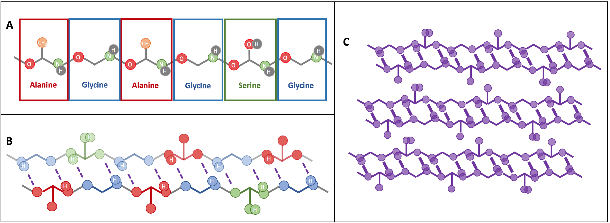
For the most part of biology, it is form that follows function. Proteins are a perfect example of this — they are made of a sequence of amino acids (the protein building units), which are synthesized by the ribosome. Once synthesized, the long strings of amino acids fold up into a particular 3D shape or conformational state. Proteins take less than a thousandth of a second to attain their preferred conformational state (called “native state”) that — if nothing goes wrong — ends up being the same for a given sequence. This process is called protein folding. Explaining how a protein finds its folding preference out of all possible ways in such a short time is a longstanding problem in biology.

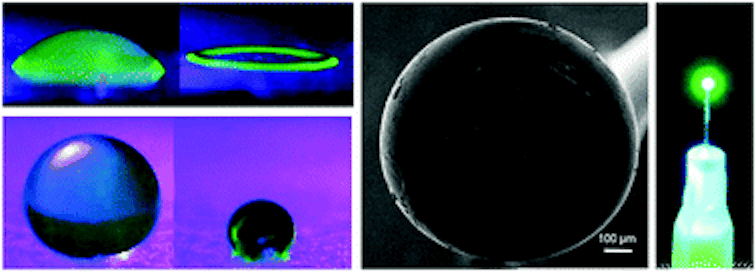
But, how do scientists know if – and when – a protein is in its folded state? The most straightforward way to do this is by observing its function — the way that a protein performs some biochemical task within the cell. If the protein is functionally active, then it has achieved its proper structure. However, most proteins are too small to observe directly without damaging the cell. To solve this problem researchers frequently use Green Fluorescent Protein (GFP), a protein that glows when it is hit by light of a specific wavelength. By attaching GFP to other proteins, researchers can see exactly where those proteins are at different timepoints. GFP’s stability, lack of interaction with other proteins, and non-toxicity make it an extremely popular candidate for visualizing protein localization. In other words, one “function” of GFP is to fluoresce. Today’s paper seeks to understand how structure correlates with function in GFP, one of biology’s most important tools.

To control the folding process, the authors used dual optical tweezers to mechanically stretch and relax the protein. Optical tweezers — as the name suggests — manipulate the position of particles (beads) using laser light. These beads are typically in the size range of micrometers. To apply forces on the GFP, the beads are attached to the protein via DNA “handles,” so that a DNA strand attached to the protein will stick to the DNA strand attached to the bead. These strands are then bound together ensuring that the force on the beads is transferred to the GFP. The construct looks as follows:

BeadDNAProteinDNABead

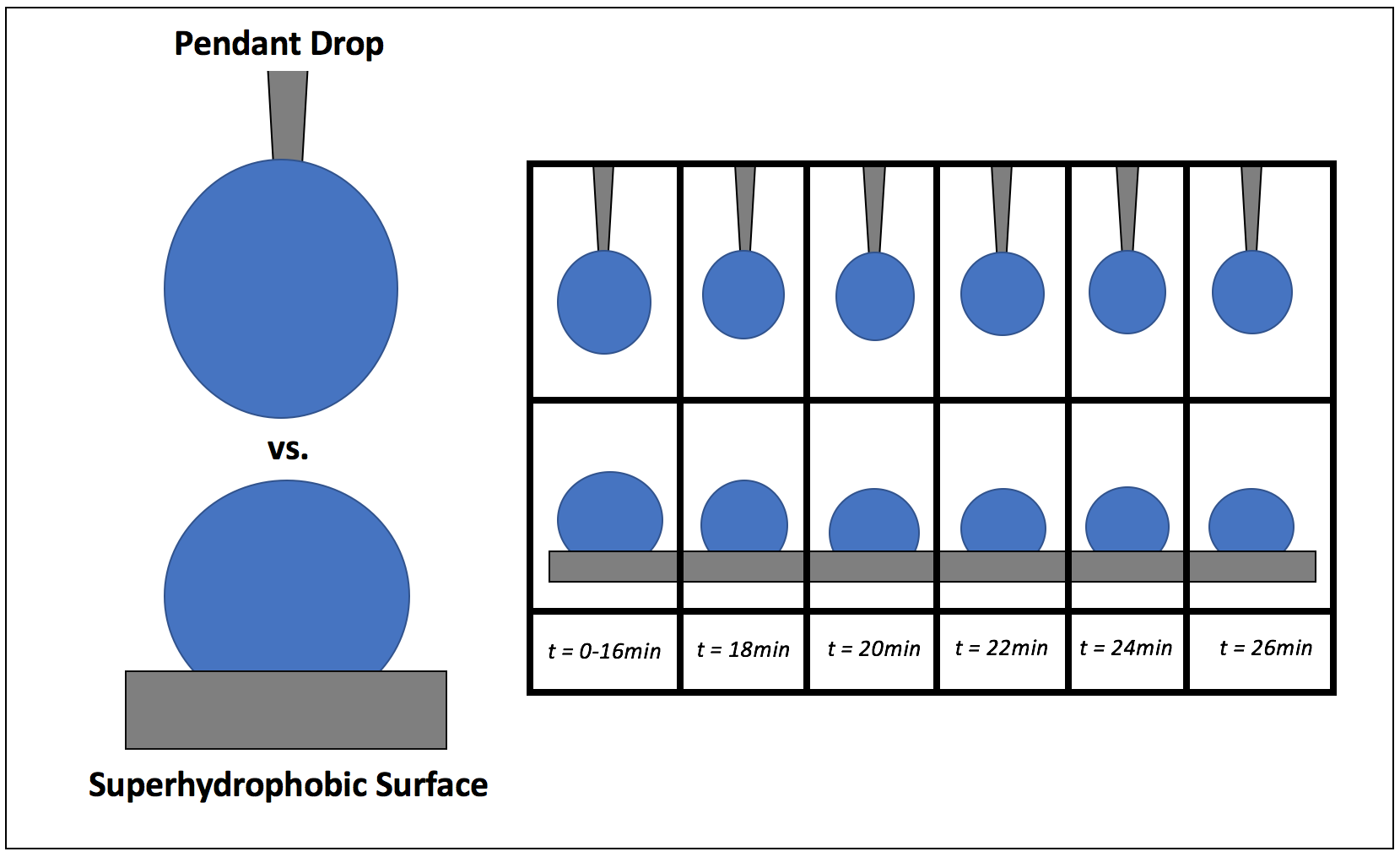
When the beads move apart, the protein is stretched to its maximal possible length (also called its contour length) and is unfolded, but when the beads get closer together, the protein folds back to its preferred structure. This process is illustrated in Figure 1.

Animation of GFP unfolding
Figure 1: The beads (circles) at each end are manipulated by laser beams and move back and forth. The DNA handles (purple) are attached to the GFP protein (green) that folds and unfolds turning to a functionally active and inactive state, respectively.

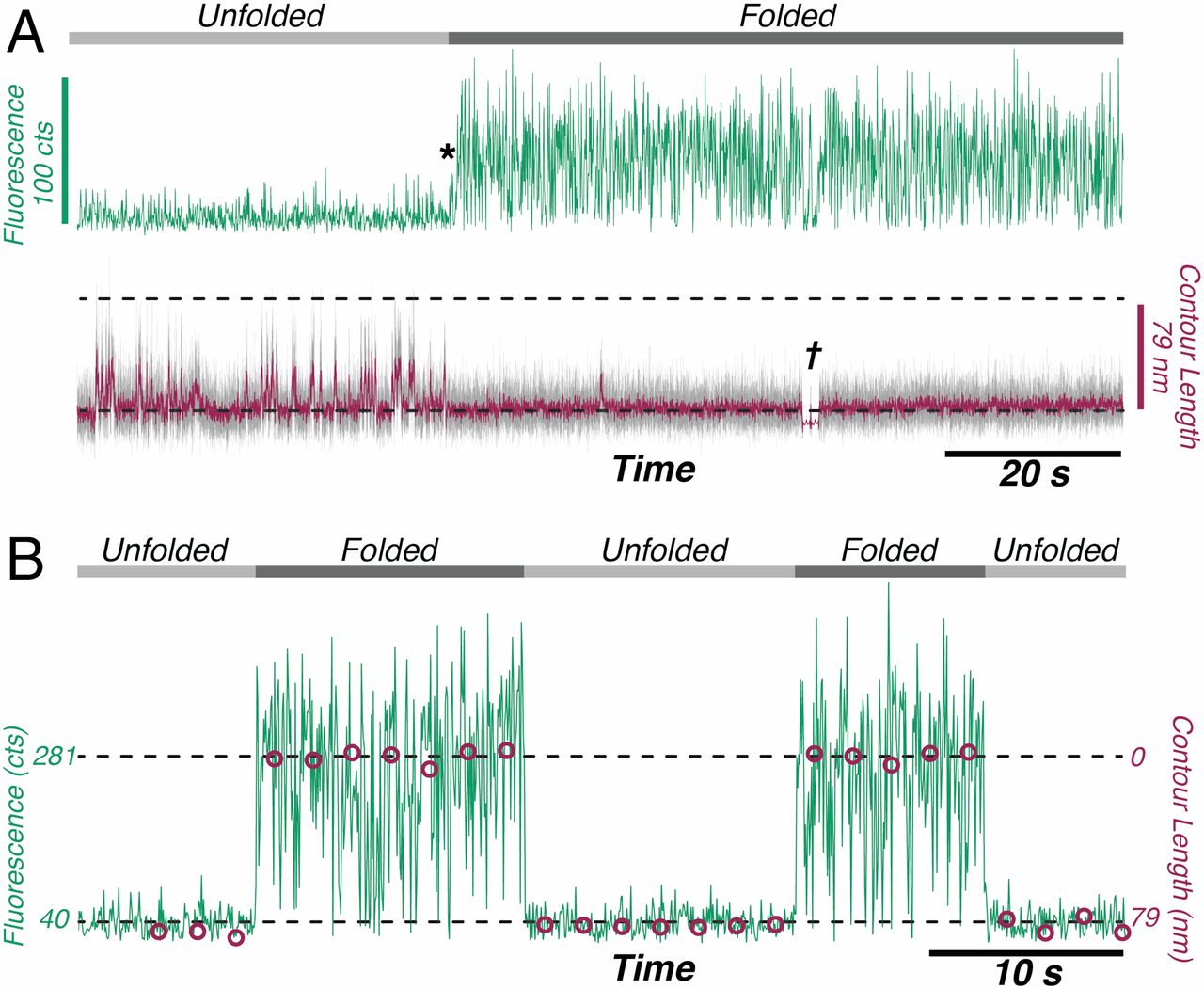
The authors observed that during unfolding, the GFP protein has undergone two intermediate states before unfolding completely. After unfolding, the beads were brought closer together and the protein folded itself back through the intermediate stages. The GFP molecule stopped emitting light when it was unfolded, which was expected. However, it started fluorescing only when it was completely in its folded state. This important finding showed that this protein is functionally inactive in any of the intermediate folding stages. The authors also observed that this process is reversible; they could unfold and refold the GFP molecule multiple times (see Figure 2).

Correlation between Fluorescence and Contour Length of the protein
Figure 2: Fluorescence signals of the GFP protein as it cycles through the unfolding and folding states. (A) The unfolded protein (light gray line) emits very little light (green signal) and its length fluctuates (purple line). Once the protein refolds (*) it emits more light and its length becomes shorter and consistent (dark gray line). † is the point where the force and state conformation are correlated(B) Cycled transition from dark (unfolded) to bright (folded). The purple circles represent the average contour length of each time. (Image adapted from Ganim’s and Rief’s paper).

These findings contribute towards understanding the functionality of proteins that could be used as in vivo optical sensors in force transduction. This work also opens up new avenues in studying biomolecules at the single-molecule level, such as DNA-protein complexes that can induce changes in conformation. Although the experiment only pulled the protein along one axis, this technique could be extended to pulling in several directions at once. If one could control the applied force in 3D, then it could be possible to gain more information on how exactly the protein folds and/or what happens during that process.

Tiny Tubes Racing in a Donut-Shaped Track

Original paper: Transition from turbulent to coherent flows in confined three-dimensional active fluids


The shape of a container can affect the flow of the fluid inside it. Water in a narrow stream flows smoothly, but once the water molecules make their way into a pond, they spread out and no longer flow coherently. If you blow into a long, narrow straw, the air will go straight through. Once the air flows into the large room you are standing in, it slows down as it mixes with the air around it, so someone standing five feet away from you won’t feel a breeze at all.

The above examples show how the shape of a container affects the flow of passive fluids. In today’s study, Kun-Ta Wu and colleagues investigated how the motion of active fluids, fluids that flow using an internal source of energy, is also affected by the shape of their container. They used a system of microtubules, chains of proteins assembled into long, stiff rods. Clusters of a protein called kinesin exert a force on microtubules by “walking” along them. Microtubules interact with each other to form swarms or turbulent-like flows.

Wu and colleagues created 3D toroidal racetracks with rectangular cross-sections to confine the microtubule bundles. They saw coherent flows in racetracks with square cross-sections, but if the channels got either too thin and wide or too tall and narrow, the flow became turbulent (Figure 1). This result is described in this Softbites post from last year.

5-1
Figure 1: Comparison of coherent and turbulent flows around a track. The left side of each track shows the motion in an instant, while the right side shows the average motion over a long time. The color represents the local direction of spinning and the black arrows indicate the direction of motion. Microtubules in a red spot are spinning clockwise, those in a yellow spot are not spinning, and those in a blue spot are spinning counterclockwise. Image adapted from original article.

After Wu and colleagues got microtubules to flow by themselves, they placed them in increasingly complicated tracks. Active flows happened in any closed loop with an approximately square cross-section. Microtubule flows solved a maze, as in Figure 2, by flowing through the connected straight and curved sections, but not sections leading to dead ends. The dead ends slowed down the flow in the connected sections to about half the speed of a toroidal racetrack with an equivalent length.

5-2
Figure 2: Microtubules flow in straight and curved sections of the maze in closed loop, and no net flow loop in sections leading to dead ends. Black arrows show the direction of the flow and colorful arrows point to sections at which mean flows are measured. Figure adapted from original article.

Wu and colleagues then created tracks made out of overlapping tori, or donuts. In the tori, microtubules spontaneously flowed in the same or in different directions, as in Figure 3. When the active flow was clockwise in one torus and counterclockwise in the other, the direction of flow in the overlap was the same, and the flow kept going (A). When they were both counterclockwise, two flows came into the overlap in opposite directions, and there was no flow in between the tori (B). Watch a video of this here.

5-3
Figure 3: Microtubules can flow in connected tori in (A) the same direction and (B) opposite directions. Figure adapted from original article.

Microtubules created an active flow when a third torus was added (Figure 4A). They also navigated a square racetrack, although the corners created small vortices and slowed them down (Figure 4B). Finally, microtubules still flowed in a very long torus made out of a 1.1 meter-long tube joined at the ends by a needle (Figure 3C).

5-4
Figure 4: (A) Flows in 3 overlapping tori. (B) Microtubules flow around a square racetrack in the direction of the blue arrow. (C) Microtubules even flowed around a very long (1.1 meter) track. The closeup shows a time-averaged flow inside a small section of the tube. Figure adapted from original article.


Thus, these flows of microtubules aren’t just a one-time phenomenon that’s hard to replicate—no matter how much the researchers changed the system, as long as there was a closed loop with an appropriate cross-sectional aspect ratio, there was a flow.

These flows inside channels are interesting—but are they useful? The researchers suggest that a system like this could act as an internal power source for very small devices, but this application is still far in the future. It is also possible that a similar motion is used inside living cells to transport materials in a process called cytoplasmic streaming. More importantly, these flows are a beautiful example of collective motion induced by physical forces, helping scientists elucidate how swarms can form at all length scales.

Self-assembling silk lasers

Rings, spheres, and optical resonators self-assembled out of silk

Original paper: 3D coffee stains


When I first learned about the coffee ring effect I thought it was super cool, but it seemed like an open-and-shut case. Why do rings form where some liquids, like spilled coffee, are left to dry? Roughness on the table causes the liquid to spread imperfectly across the surface, pinning the edges of the droplet in place with a fixed diameter. Because the diameter of the droplet can’t change during evaporation, new liquid must flow from the droplet’s center to the edges. This flow also pushes dissolved coffee particles to the edges of the droplet, where they are left behind to form a ring as the water evaporates away (Figure 1). More details can be found in our previous post, here. It’s a complicated phenomenon, but after being described in 1997 it doesn’t seem like anything new would be going on here. Right? Well, as usually happens in science, classic concepts have a way of popping back up in unexpected ways. Last year It?r Bak?? Do?ru and her colleagues in Prof. Nizamo?lu’s group at Koç University, Turkey published a study using the often troublesome coffee ring effect to their advantage: making self-assembling silk lasers.

pinning
Figure 1: Pinning and the Coffee Ring Effect. A cross section of a water droplet drying on a smooth surface (A) versus a rough surface (B). On a smooth surface the droplet shrinks due to evaporation. On a rough surface the edge of the droplet is pinned and cannot shrink, forcing an internal flow to maintain the droplet’s shape.

The fundamentals here are the same as the classic coffee ring effect, but instead of coffee particles Do?ru’s droplets hold a colloidal suspension of silk fibroin proteins. In a colloidal suspension, particles (such as proteins) are mixed in another material (such as water) and neither dissolve fully into solution nor precipitate out. Smoke, milk, and jelly are all examples of colloids. Harnessing the coffee ring effect to build 2D structures out of colloidal particles has been well developed since Witten’s description of the coffee ring effect in 1997 [1], but 3D self-assembly is much less common. What makes Do?ru’s 3D structures possible is the fibroin protein.

Fibroin is the primary component of silk from the silkworm Bombyx mori. These fibers have been used by humans for thousands of years to make textiles, but recently the fibroin protein has taken on new life when extracted from silk as an aqueous, water-based, suspension and regenerated into other forms [2,3]. Fibroin proteins are long, and they easily tangle up and bond to each other to form networks of layered crystalline structures called beta-sheets (?-sheets) (Figure 2). These sheets give silk fibers and other fibroin materials strength and toughness. Furthermore, fibroin materials are biocompatible and biodegradable.

Silk Fibroin and Beta Sheets
Figure 2: Silk Fibroin And ?-sheets. Silk is made of long fibroin proteins (a) that have a repeating molecular structure. These proteins bond together into ?-sheets (b), which then stack together (c) to form materials with high strength and toughness.

To create 3D structures with the coffee ring effect, Do?ru, Nizamo?lu, and their coworkers put droplets of silk solution on superhydrophobic surfaces. Superhydrophobic surfaces strongly repel water, preventing water-based liquids from spreading flat across the surface and making the droplets stand straight up during the drying process. This makes the angle between the edge of the droplet and the surface (called the contact angle) particularly high, between 95-145 degrees throughout evaporation. The interaction between water and the superhydrophobic surface determines the shape of the final structure, with high contact angles creating more spherical droplets (Figure 3). After a solid 2D ring of fibroin forms on the bottom, the silk proteins continue to stack along the droplet’s surface, forming a stable spherical shell of ?-sheets that the remaining water can evaporate through. The researchers found that the concentration of the fibroin solution was important for controlling the final structure. If the solution is too dilute then the shell will collapse in on itself, but if the fibroin concentration is too high the initial contact angle will be lower and the final structure will also be more 2D than 3D.

Contact Angle
Figure 3: Contact Angle. Droplets of the same solution show different contact angles on different surfaces (as adapted from Do?ru’s paper). On the left is a mildly hydrophobic surface, and on the right is a superhydrophobic surface. Note how the size of the contact angle (shown in white) increases with the hydrophobicity of the surface.

To make 3D spheres, the researchers tried the pendant drop method, hanging a droplet from the tip of a needle. Similar to getting high contact angles from a droplet on a hydrophobic surface, hanging a droplet from a needle gives that droplet a small contact area, and a spherical shape (Figure 4). If the diameter of the needle is the same size or smaller than the contact area of the droplet on a superhydrophobic surface, then the shape of a droplet squeezed out of the needle should be as or more spherical than the droplets in the previous experiment. In this study, the pendant drop method ends up producing more uniform drying. These pendant-drop shells are smooth enough inside to act as optical resonators, surfaces that reflect light waves back on themselves so the waves amplify each other (the “a” in “laser,” which I always forget comes from the acronym for “light amplification by stimulated emission of radiation”).

As a proof of concept, the researchers made shells out of fibroin mixed with green fluorescent protein (GFP). Fibroin ?-sheet formation is so stable that it still happens when small amounts of other materials are present, so the optical resonator can form in the same way it did with a fibroin-only solution. In this case, because GFP has been added, when the structure is exposed to the right light source it will amplify green light emitted by the shell itself – an “all protein laser” in the making.

Benefits of the Hanging Pendant Drop
Figure 4: Benefits of the Hanging Pendant Drop. The hanging pendant drop method can produce similar spherical drops to a hydrophobic surface. It was shown that the pendant drop method produces more spherical final structures (adapted from Do?ru’s paper).

Part of what’s exciting about this publication is that the authors harness the coffee ring effect for a fun new type of small scale, self-directed 3D “printing.” They showed that the method works for other polymers as well, but I agree with their choice to highlight the silk protein fibroin. Not only is fibroin biocompatible, but it also has the potential to be more environmentally friendly to process than other polymers and is already produced in large quantities globally as part of the textile industry.


[1] Han, W. and Lin, Z. “Learning from ‘Coffee Rings’: Ordered Structures Enabled by Controlled Evaporative Self-Assembly.” Angew. Chem. Int. Ed. 51 (2012): 1534–1546.

[2] Altman, G.H. et al. “Silk-based biomaterials.” Biomaterials 24 (2003): 401–416.

[3] Koh, L.-D. et al. “Structures, mechanical properties and applications of silk fibroin materials.” Prog. Polym. Sci. 46 (2015): 86–110.