Fast Flow in Tiny Tubes

Original Paper: Massive radius-dependent flow slippage in carbon nanotubes


Water is made up of many many molecules of H_2O. But when you drink it from a glass or take a shower, this doesn’t matter. A typical fluid is so much bigger than an individual molecule that you can just treat it as a continuum: if you shoot water out of a hose with some initial velocity, you can use physics to figure out where the water will land without having the consider the motion of all the molecules. Considering each molecule would get the same result, but would be a vastly more difficult calculation. However, when the fluid is very small, not much larger than the size of individual molecules, then the molecular nature of water starts to matter. The “continuum breakdown” is an intriguing aspect of fluid mechanics and physics in general, but is typically very hard to study experimentally. Recently, a group of researchers based in France overcame these difficulties and managed to study water flowing through carbon nanotubes (Figure 1).

Experiment schematic
Figure 1: Left: an electron microscope image of a carbon nanotube inside a glass microcapillary. Right: a cartoon of water flowing out of the tube. Adapted from Figure 1.

When does it matter that the fluid is made of molecules? One of the implications of the molecular nature of a liquid has to do with what happens when it flows along a wall (e.g. inside a pipe). There is an assumption that the friction between the wall and the fluid will halt the flow right next to the walls, and the fluid will increase in speed farther from the walls. This is called the “no-slip” boundary condition and is a pretty central concept in fluid mechanics that makes the relevant equations much simpler (Figure 2). It is known that this condition is not perfectly true at the molecular scale. There may still be some net motion of fluid right next to the walls leading to slightly faster flow than expected from no-slip conditions because the lack of zero-velocity fluid would mean the average flow rate is higher. The exact nature of the boundary condition depends on the interaction between the molecules of the fluid and the molecules of the wall, and this doesn’t matter when the fluid is so much bigger than the region near the interface.

no slip cow
Figure 2: The slower wind speeds near the surface of the cow are an example of no-slip boundaries in action, where friction between the surface and the air causes the air to slow down. Yes, this was the best demonstration I could find of this.

The ideal way to investigate how molecular interactions affect flow near an interface would be to send fluid through something that is both very narrow and also very long compared to its width (narrow so that a large fraction of the molecules are near the wall, long so that the molecules spend more time in the tube and can be studied more easily). A water molecule is about 0.1 nanometers wide, so ideally the potential conduit wouldn’t be too much wider (for scale, a human hair is about 50,000 nanometers thick). Carbon nanotubes, which are one atom thick like graphene but wrapped into a cylinder instead of a sheet, are pretty close to the ideal: the skinniest is as small as a few nanometers in diameter and up to thousands of times as long. Of course, “just flow water through a carbon nanotube” is easier said than done.

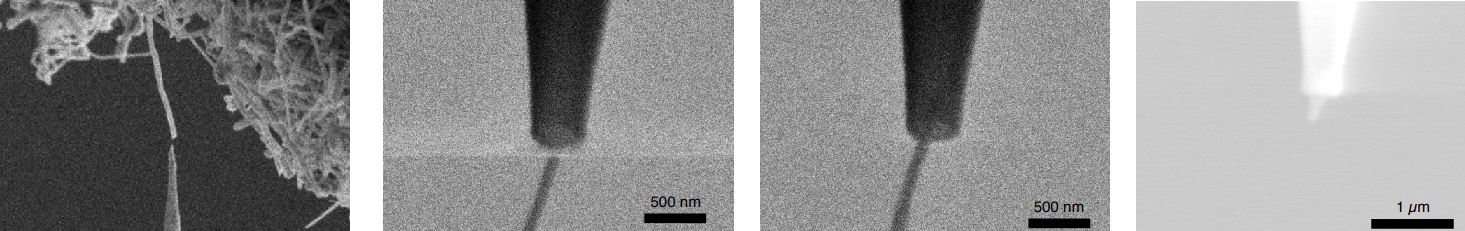
The way to do this is to insert it into a slightly-bigger-but-still-small tube, which in this experiment was done with a glass capillary, which, being from the Latin word capillus meaning hair, is a tube so narrow it looks like a hair. A sharp tip was used to pull a single carbon nanotube out of a big tangled mess of carbon nanotubes called a “forest” (this is how they are arranged when you buy them). Then, the researchers carefully inserted the nanotube into the narrow end of the glass capillary, and the gap between the nanotube and the capillary was sealed. All of this was monitored in real time using a microscope (Figure 3). I recommend reading the Section 1 of the Supplemental Methods, it’s quite fascinating and not too technical. There is also a video of it here.

I met one of the authors of the paper, Derek Stein of Brown University when I visited his lab in 2015. He showed me a prototype of this experiment, and ribaldly described the process of inserting the carbon nanotube into the glass capillary as “nano-sex.” My father is a urologist and might describe this as the world’s smallest catheterization.  

SWNT insertion
Figure 3: A carbon nanotube was pulled from a “forest” and then inserted into a glass capillary tube. Adapted from Supplementary Figures 1 and 3.

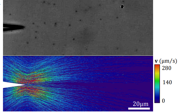
Once the tiny tube (the carbon nanotube) was hooked up to the less-tiny tube (the glass capillary), it was simply a matter of connecting two fluid reservoirs with the composite tube, applying pressure to one side, and measuring the rate at which water flows into the other side. To do this, they put fluorescent beads in the water and observed their motion near the exit of the tube. From the speed of the beads near the tube exit, they were able to figure out how fast the fluid must be flowing (Figure 4).

SWNT flow
Figure 4: Top: A microscope image of the nozzle and some beads (I have enhanced the contrast to make the beads more visible. The big black thing at the top right is probably gunk on the microscope or camera). Bottom: The speeds of the beads (no rhyme intended) at different points around the nozzle, as determined from their motion over time. Adapted from Supplementary Figure 9.

Then, by examining the relationship between applied pressure, the measured flow velocity, and the geometry of the nanotubes, the researchers were able to measure something called the fluid permeability of the system. This quantifies how well fluids can flow through the system, analogous to the electrical conductivity of a metal. Since it is known how a fluid behaves in a tube of a given radius with perfect no-slip conditions, the team compared their measurements to those expectations. What they found was that for larger nanotubes, the results were fairly consistent with no-slip, but as the tubes got smaller and a higher proportion of the water molecules come into contact with the interface, the fluid flowed a lot faster than expected (Figure 5). In the smallest tubes, it flowed 25 times faster than expected. The velocity at the walls was not actually zero, and the flow rate was consistent with a tube with twenty times larger in diameter than the one that was actually used — a big enough result to title the paper: Massive radius-dependent flow slippage in carbon nanotubes.

no slip vs. slip
Figure 5: We treat fluids as if they flow like on the left, but in carbon nanotubes, it was more like on the right.

Why does the interaction between carbon and water lead to such massive slipping? This isn’t actually known, but at the atomic scale, friction is due to electrical interactions between the atoms that make up the nanotubes and the water. Carbon nanotubes are fairly conductive, meaning the electrons aren’t that strongly bound to atomic nuclei. The authors hypothesized that an insulating tube with the same chemical structure as a carbon nanotube would have different flow properties. Fortunately, such a thing does exist: boron nitride nanotubes. They did the same type of experiment with the insulating tubes and found that the water flowed much slower than the version with the conducting carbon nanotubes. This actually surprised them— they expected a difference, but not such a big one and they had no explanation for it:

“That these nearly identical channels exhibit very different surface flow dynamics is unexpected… simulations predict that the friction of water on carbon surfaces is lower than on boron nitride surfaces, but even these predictions strongly underestimate the difference observed here.”

Traditional solid-state physics, which deals with the electronic and magnetic properties of crystalline materials, doesn’t usually intersect with soft condensed matter physics, which deals with flowy squishier things. This experiment, showing that the way a fluid flows through a tube depends on the electrical properties of the tube, is taking a step towards bringing them together, even though its results aren’t yet fully explained.

Fluids That Flow Themselves

Original paper: Transition from turbulent to coherent flows in confined three-dimensional active fluids  (Non-paywall version here.)

Disclosure: The first author of the paper discussed in this post, Kun-Ta Wu, did his Ph.D. at New York University, in the same research group as the present writer (CPK). At NYU, both Wu and CPK worked on topics unrelated to the research discussed here.

*****

When we think about fluid flow, we generally think of motion in response to some external force: rivers run downhill because of gravity, while soda moves through a straw because of the pressure difference created by sucking on one end. Recently, however, scientists have become interested in a class of fluids that have the capacity to move all by themselves — the so-called “active fluids.” Active materials — of which active fluids are a subset — are distinct from regular materials because energy is injected into the system at the level of individual molecules. In today’s paper, Kun-Ta Wu and his co-workers explore how such a material can turn its stored chemical energy into useful work: cargo transport.

Why are active materials so interesting? For one thing, many biological systems are active — for example the actin filaments that drive muscle contraction or bacterial swarms. Although active systems are both common and important in our everyday lives, the physical laws that govern their behavior are not well understood [1]. Studying artificial active systems, which are much simpler than living ones, might give us insight into this difficult problem.

As well as helping us to understand basic physics and biology, Wu and his co-workers hope that their research will move us closer to producing artificial materials that transport cargo without adding energy from an external source — a self–powered fluidic conveyer belt [2]. Such a material would be totally different from those that we currently use, and would greatly expand the possibilities available to engineers in fields such as microfluidics and soft robotics.

Wu’s research focuses on a system made up of protein molecules that assemble into cylindrical rods called microtubules. While microtubules are very important in biology [3], Wu uses these tiny rods, suspended in water, to make an artificial active fluid. As well as microtubules, Wu adds two other critical ingredients: kinesin molecular motors, and ATP (adenosine triphosphate), a chemical that many biological systems use as an energy source [4].

fig1
A sliding force is generated between microtubules by the action of molecular motors. (Adapted from Figure 1 of the original paper.)

A single kinesin molecule attaches to two parallel microtubules and creates a lateral force that slides or “walks” them along each other. A single “step” of this walk involves a chemical reaction that converts one ATP molecule into ADP (adenosine diphosphate), a lower-energy state, thereby converting chemical potential energy into motion. A collection of millions or billions of microtubules (and a similar number of kinesin and ATP molecules) forms a material that writhes and squirms without any forces acting upon it. In the following video, Wu records the motion of both the microtubules themselves (they’re tagged with a fluorescent red dye), and micrometer-sized green particles, which he uses to trace the flow.

Video 1 Using fluorescence microscopy, Wu and colleagues can observe the motion of microtubules (red), as well as test cargo — colloidal particles (green) that are carried along in the flow generated by the motion of microtubules. (Movie 1 of the original paper.)

.
But converting energy into useful work doesn’t just require motion; it requires motion that is controlled, directed, and uniform over time — coherent motion. This brings us to the main finding of Wu and coworkers: in the microtubules-motors-ATP system, coherent motion can be produced by controlling the shape of the container. Placed in a large rectangular box, the flow in the middle of the box (“in the bulk”) is turbulent but directionless (see panel A of the below figure). However, when placed in a ring with appropriate dimensions, the flow spontaneously organizes into large-scale circular patterns that are capable of transporting cargo — like fluorescent colloidal particles — over lengths of centimeters or even longer (panel B below).

fig2
Panel A shows the pattern of flow of a bulk sample of active fluid. The arrows represent the velocity field, and colors represent the normalized vorticity of the flow: the extent to which it is rotating clockwise or anticlockwise in a local frame of reference. The left half of the panel shows a snapshot of the flow at a single instant in time, while the right half shows the time average. (This convention is also used in the other flow visualizations shown in this post.) In the time-averaged plot, both velocity and vorticity are almost zero: the flow is turbulent but directionless. Panel B-i shows the ring geometry of one of the sample chambers Wu uses to create coherent flow, and B-ii shows the flow pattern in that chamber. Unlike in the bulk sample, a long-lived circular pattern is generated that pushes the cargo around the ring. (Adapted from Figure 1 of the original paper.)

Interestingly, whether or not this happens is controlled only by the aspect ratio of the container: the channel width divided by its height [5]. Coherent flow is observed when the aspect ratio is between ? and 3; in other words, it disappears if the ring is too flat or too tall. Additionally, Wu shows that the direction of the flow– whether it goes clockwise or counterclockwise —  can be controlled by decorating the outside of the container with appropriately shaped notches, which Wu calls ratchets.

Finally, the researchers show that the appearance of directed flow coincides with the onset of nematic order: in circulating samples, the rod-like microtubules tend to align with their neighbors, while in the turbulent samples, they are oriented randomly. According to Wu, this alignment allows the fluid to collectively push itself off the walls of the container, thus generating global circulation.

fig3
Wu and co-workers use ratchets — small asymmetrical notches on the outside of the ring — to control whether the flow is clockwise (CW) or counterclockwise (CCW). The scale bar shows that flow is coherent over lengths of centimeters. (Adapted from Figure 3 of the original paper.)

Of course, this paper only scratches the surface of the technological potential of active materials. Research on this, and similar ideas, continues both at Brandeis University, where this research was done, and in Worcester Polytechnical Institute, where Wu has recently been appointed professor. Here, according to his website, Wu aims to “advance our understanding of self-organization of active matter as well as to create unprecedented bio-inspired materials.”

*****

[1] Physical systems at thermodynamic equilibrium obey the Boltzmann distribution — a formula that (in principle) allows us to calculate macroscopic properties of many-body systems, if we know the interactions between the constituent particles. We don’t know of a similar theory that describes the behavior of out-of-equilibrium systems, and active systems are by definition out of equilibrium.  

[2] Of course, the energy ultimately has to come from somewhere. In the case of the material studied by Wu et al, the conveyer belt would have to be “charged” with fresh ATP before use.

[3] In particular, microtubules are the most important structural component of the mitotic spindle – the sub-cellular structure that pulls chromosomes copies apart during cell division.

[4] Wu also adds a chemical known as a depletant, which makes the microtubules bundle together, allowing the kinesin to slide them along each other.

[5] Wu also studies cylinders and shows that a similar geometrical parameter controls the appearance of coherent flow.